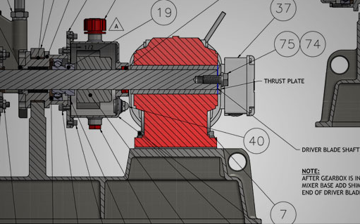
Computer Aided Design, more commonly known as CAD, is the use of software to create or modify parts or a compilation of parts. Beginning with AutoCAD back in 1982, CAD software has assisted engineers throughout the design process. Now, there are even further innovations demonstrated in commonly used software such as Autodesk Inventor and SolidWorks. These allow engineers to not only improve their design process but increase efficiency as well. Yet, before these programs came to light though, every schematic was drawn by hand. It’s hard to even imagine that with technology these days. Let’s take a look at how CAD has influenced the process equipment industry.
The most clearly outlined benefit of CAD software is the ability to create virtual properties that model the intended finished product. This streamlines the workflow and speeds up design process considerably. Another caveat that is solved from moving away from paper is the ease of changes and revision history. No longer are the days of paper, pencil and worn out eraser. The accuracy that comes with it is hard to argue. Vector images are defined by mathematical coordinates and grid snapped allows all objects to be drawn on a rectangular grid. This ensures accuracy in length, area, and volume or the piece. What some may not know, is that it also offers the opportunity to perform analysis of the product without the manufacturing of a physical prototype. Many CAD programs these days allow for stress tests, pressure and many other parameters.
There’s a reason SolidWorks is one of the most popular programs for engineers. Not only is it extremely user friendly compared to other options, but you can even start with a 2D sketch. Once the initial sketch is completed, dimensions can then be added to define size and location of the piece. By creating 3D solids within numeric and geometric parameters, it allows stringent requirements to be met while still increasing the overall efficiency of the design. SolidWorks Simulation even gives you a number of options including materials, fixtures, connections, and external loads. This is what essentially creates a virtual prototype, capable of undergoing tests for stresses, strains and displacements. Last but not least, these vector images can be translated into g-code, which is directly imported for use within CNC machines.
Despite the many benefits of CAD software, it does still have some downfalls, which sends some engineers back to their paper pad. For many, sketching is still extremely beneficial for visual problem solving and often speeds up this process. Some feel that these programs put constraints on thinking and drafting of a project as you’re required to work within their parameters. Despite their visual appeal, jumping right into drafting without problem solving first may cause problems with the machinery moving forward. All in all, users must make sure not to dwell so much on the virtual object that it causes.
Bethany. (2018, August 01). How Engineers Use Computer Aided Design. Retrieved from https://www.scan2cad.com/cad/how-engineers-use-cad/
Computer-Aided Design (CAD) and Computer-Aided Manufacturing (CAM) – Encyclopedia – Business Terms. (-0001, November 30). Retrieved from https://www.inc.com/encyclopedia/computer-aided-design-cad-and-computer-aided-cam.html


